Drift Tube Ion Mobility Spectrometry (DT-IMS) is an analytical method based on the time dispersion of ions in the gas phase at atmospheric pressure. In this technique, the analyte is vaporized and enters the ionization region, where the analyte molecules undergo ionization. The gas-phase ions are periodically introduced as ion packets into the drift region by applying successive pulses to the ion gate. An electric field is applied to propel the ion swarms across the drift tube toward the collector. As the charged molecules travel through the drift tube, they are efficiently separated based on their intrinsic speeds, which depend on their size, mass, and geometry. Each ion bunch generates a peak in ion current recorded by the collector at the corresponding arrival time. The drift time of each peak is utilized for qualitative analysis, while the intensity of the ion signals correlates with the concentration of the analyte. In summary, detection and measurement are achieved by detecting ions that are associated with the analyte.

A typical clean positive ion mobility spectrum consists of three background peaks known as reactant ions, namely NH4+, NO+, and H3O+, which are primarily generated by the ion source. When analyte A is introduced into the ionization region, a charge transfer or proton transfer reaction occurs, resulting in the appearance of a new peak at a longer drift time, while the intensity of the reactant ion peaks decreases.
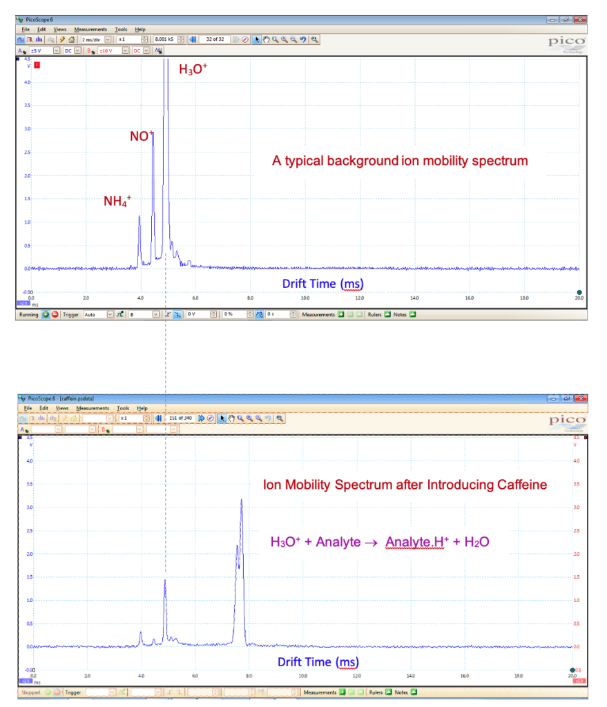
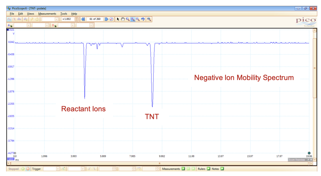
With hydronium or ammonium reactant ions, IMS exhibits high sensitivity towards compounds that have a high proton affinity, such as amines, ketones, organophosphate pesticides, alkaloids, and drugs of abuse. IMS is also capable of operating in the negative mode to detect negative ions. In the negative mode, the typical reactant ions include O2–, NOx–, O3–, and OH–. Compounds that possess a high electron affinity, such as those containing halogens or nitro groups, are best detected in the negative mode.
IMS, by its nature, is a chromatography technique. In IMS, the drift tube can be likened to the column in GC. An ion packet is introduced into the drift tube (column) through the shutter grid. The electric field acts as the carrier gas, pushing the analyte (ions) inside the column (drift tube). Therefore, IMS was initially referred to as plasma chromatography since a mixture of ions (plasma) is separated within the drift tube (column). The key distinction is that, unlike GC or HPLC, a complete chromatogram is obtained in just 20 ms, making it a thousand times faster. For each sample injection, hundreds of spectra are recorded in less than a minute. The column is composed of a halo tube, unlike GC, and does not require any changes or maintenance nor is it prone to damage from oxygen or water vapor. Due to the high temperature and the use of clean gas during operation, the drift tube in IMS undergoes effective cleaning and becomes readily available for the subsequent run. Consequently, repetitive measurements can be conducted within a short period of time.
IMS may also be compared to the Time-of-Flight Mass Spectrometer (TOF-MS). The big difference is that IMS, unlike MS that needs vacuum, it operates under atmospheric pressure. Hence, no need to vacuum pumps. This cuts the price of an IMS to a fraction of a MS and further simplifies the instrument, making it almost maintenance-free. Although the resolution is not as good as MS, IMS can separate most compounds of interest as they differ in mass by several amus. The big advantage is atmospheric pressure sampling and soft chemical ionization in ambient pressure. The unique advantage of IMS over mass spectrometry is the separation of isomers because IMS is sensitive to size. Nowadays, an IMS is used prior to an advanced mass spectrometer to differentiate isomers.
IMS can also be compared to Time-of-Flight Mass Spectrometry (TOF-MS). The key distinction is that IMS operates under atmospheric pressure, unlike MS, which requires a vacuum. This eliminates the need for vacuum pumps and significantly reduces the cost of IMS compared to MS, making the instrument simpler and almost maintenance-free. In TOF-MS, ions are accelerated and then travel in a vacuum field-free region, while in IMS, ions are continuously subjected to an electric field within a gaseous medium. They reach a limit velocity (V) determined by their intrinsic mobility (K) and the intensity of the electric field (E), such that V = K.E. Although the resolution of IMS may not be as high as MS, it is still capable of separating most compounds of interest that differ in mass by several atomic mass units. The significant advantage of IMS lies in its ability to accept samples at ambient pressure and utilize soft atmospheric pressure chemical ionization. One unique advantage of IMS over mass spectrometry is its ability to separate isomers based on their size. Nowadays, IMS is often employed prior to advanced mass spectrometers to differentiate between isomers.
Multi Ion Source IMS
The MIS-IMS technology offers rapid analysis time, high selectivity, and high separation. Its combination of specificity, speed, sensitivity, and ease of use makes it an excellent alternative to many routine detection and quantification techniques.
Instrumentation
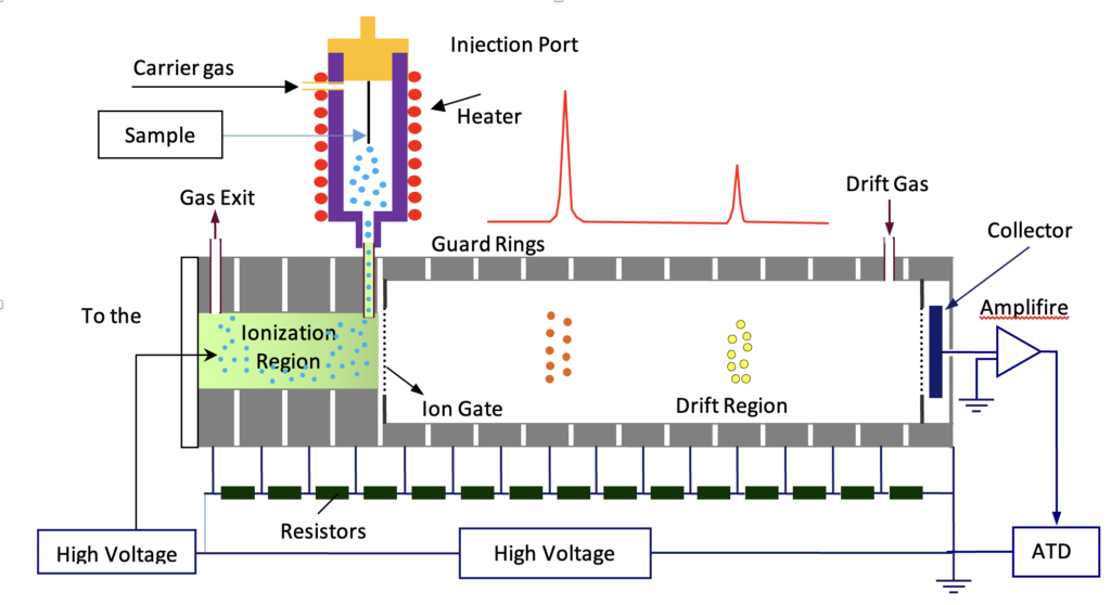
An IMS primarily consists of an ion source, a drift tube, an ion gate, a collector, an amplifier, and a digital oscilloscope for recording spectra. A high-voltage power supply, typically around 10 kV, is utilized to establish the electric field. Depending on the ionization source, a second power supply may be required. A pulse generator is employed to drive the ion gate by applying a perpendicular field to the traveling ions. The sample is introduced through a suitable injection port, which may vary depending on whether it is a gas, liquid, or solid. A carrier gas is employed to transport the sample vapor into the ionization region. A second clean gas, known as the drift gas, is directed into the drift tube in a counterflow direction to the moving ions. Its purpose is to maintain the drift tube free from sample contaminants.
Drift Tube
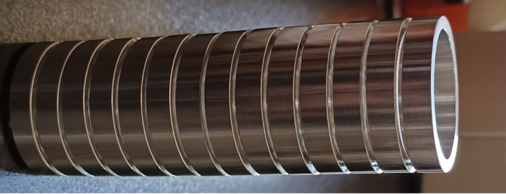
Consists of a series of interconnected metal rings that are linked together by resistors. The high voltage is applied uniformly across the entire tube to generate an electric field within it. The resistors act as a voltage divider to evenly distribute the voltage to the rings. This results in the creation of a homogeneous electric field inside the tube, facilitating the movement of ions towards the collector. The polarity of the field determines whether positive or negative ions are directed towards the collector. To elevate the temperature of the drift tube, a heater and thermostat are utilized.
Ion Gate
An ion gate or shutter grid is positioned between the ionization and drift regions in the IMS setup. Its role is to regulate the entry of ions into the drift tube by either permitting or preventing their passage. The ion gate typically follows the design of the Bradbury-Nielson type, comprising two sets of parallel wires mounted on an insulator frame. This component is crucial for the IMS system and requires precision. The wires are approximately 100 microns in diameter and are spaced one millimeter apart on a ceramic frame. It is essential for the wires to be accurately parallel and remain straight even at high temperatures.
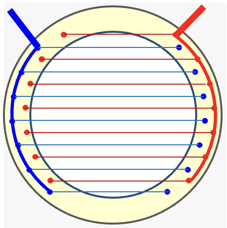

The Shutter Grid consists of two sets of parallel wires fixed on an insulating frame.
The shutter grid is positioned perpendicular to the direction of ion movement. When the wires are connected to the same potential, ions are allowed to pass through. However, when a sufficient voltage difference is applied between the wires, the ions are annihilated on the wires. The wires are connected to a pulse generator that periodically opens and closes the gate. This pulsing mechanism enables the gate to open briefly, generating a narrow ion packet that is then introduced into the drift tube.

Ion Mobility
In an IMS device, ions move at atmospheric pressure within a drift tube under the influence of an electric field. The velocity of an ion, denoted as v, is directly related to the applied electric field, represented by E.

The coefficient K represents the ion mobility and is influenced not only by the size, shape, and mass of the ion but also by factors such as pressure, temperature, and the properties of the buffer gas in which the ion travels. To determine ion mobility, the drift time is measured using an ion mobility spectrometer, which consists of a known drift length and an established electric field.
![]()
In this equation, D represents the drift length, td signifies the drift time, and E refers to the electric field within the drift tube.
Ion mobility provides valuable insights into the characteristics of ions, allowing for the differentiation and analysis of various compounds based on their distinct mobility behavior within the IMS system. Theoretically, it can be calculated using the Mason-Schamp Equation.

Where, q is the ion charge, N is the drift gas number density, μ is the reduced mass of the ion and the drift gas molecules, k is the Boltzmann constant, T is the drift gas temperature, and Ω is the collision cross section between the ion and the drift gas molecules, that represents the size.
Standard Mobility
Ion mobility is influenced by environmental conditions like temperature and pressure. It is usually reported based on reduced values to the standard condition to account for environmental conditions.

Where T and P are the temperature and pressure of the drift tube in Kelvin and Torr, respectively. Ko is the standard mobility or reduced mobility. Standard mobility is also often reported based on a reference;

Where td (std) is the drift time of a known ion with standard mobility of Ko (Std), and td (Sample) is the drift time of the sample. The standard mobility, as determined by the ion mobility spectrometer, is employed for sample identification purposes.